Technical parameters
| model |
|
| Processing steel bar diameter |
Φ 12-50mm |
| Rated bending speed |
38.4°/s |
| Bending machine moving speed |
0.5-0.9m/s |
|
bending angle |
Positive bend 0-180° |
| Reverse bend 0-120° |
| Installed power |
24Kw |
| Maximum conveyor roller load-bearing capacity |
1000Kg |
| Minimum center distance of bending head |
1200mm |
| Maximum center distance of bending machine head |
13000mm |
| Equipment dimensions |
12.5mx2.5mx1. 5m |
| Equipment weight |
About 7 tons |
Operation Procedure
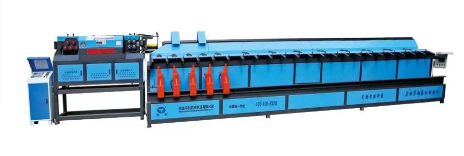
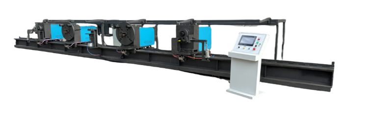
Before installing this equipment, a reinforced concrete foundation must be cast. The cement concrete foundation must comply with national equipment foundation specifications. Power and signal cables, etc., must be routed through the pre-buried conduit. The production line layout is primarily divided into three areas: the rebar raw material storage area, the rebar bending machine head operating area, and the storage and processing of finished products. Transportation and subsequent processing must be streamlined.
During commissioning, to ensure safety, only the commissioning personnel may operate electrical switches and buttons. No one else is permitted to operate these switches or buttons.
(1) Before commissioning
① First, check the fasteners and connectors of each part to ensure that there is no looseness;
② Check the lubrication of each lubricated part and the oil level of the reducer and air compressor;
(2) No-load test
Let the motor and transmission part work and run at no-load for at least 5 minutes. During no-load operation, pay attention to
1. Check the direction of rotation of the motor;
2. Check the action of the cylinder;
3. Check the photoelectric detection signal;
4. Check whether the steel bar clamps are moving in unison;
5. Check whether the smooth operation of all movements of the entire machine is normal;
6. After stopping the machine, change the speed and then perform a test run according to 1-5 above.
(3) Test run with load.
① Perform a manual test run;
② Perform an automatic test run.
③ After the automatic test run is normal, train the personnel and the machine can be put into use after the training is completed.